
In an Isa hierarchy only the root entity set has a key and it must serve as the key for all entities in the hierarchy. The Crows Foot notation is often used in ER models to how a.

Entity Relationship Diagram Erd Er Diagram Tutorial
By nature it is an abstract visualization the first step in the design process towards creating a logical and functional database.
Erd maker with isa. However its only useful to define subtypes if theyll have their own attributes or relationships. However in one there are two ISA triangles from the Entity Movie and in the other there is just one. Entity-Relationship Model ER Diagrams Weak Entity Sets Converting ER Diagrams to Relations.
ERDPlus is a web-based database modeling tool that lets you quickly and easily create. An ERD contains different symbols and connectors that visualize two important information. Let SmartDraws ERD diagram tool make it easy.
What is the difference in meaning. Assuming the relationship is mandatory as you said a person has to be a student or a teacher and disjoint a person is either a student or a teacher but not both the best solution is with 2 tables one for students and one for teachers. Since then Charles Bachman and James Martin have added some slight refinements to the basic ERD principles.
The ERD diagramming tool has all the ERD symbols and connectors you need to create professional industry-standard ER model. 2 Purpose of ER Model The ER model allows us to sketch. The History of Entity Relationship Diagrams.
Create and connect shapes with drag and drop. An ER diagram is a means of visualizing how the information a system produces is related. Cross-platform Windows Mac Linux and compatible with all web browsers.
The originator of Crows Foot notation was Gordon Everest who offered the idea of how to visually represent the different types of relationships that can exist between objects in an entity relationship diagram ERD. To identify entitities that participate in a relationship. Reasons for using ISA.
In an ER Diagram entities are the most important parts. For example the elements writer novel and a consumer may be described using ER diagrams the following way. Entities are typically nouns such as car bank student or product.
Istilah dan Komponen Penyusun ERD. ER modeling enables you to assess details requirements systematically to make a well-made data source. Visual Paradigms online ERD software makes database design fast and straight-forward.
Include tables fields and primary or. Panduan Lengkap Cara Membuat Database WordPress di MYSQL. No matter you want to create a conceptual logical or physical data model our online ERD tool just works perfectly.
You can use them to illustrate how data is structured in business processes or to detail how data is stored within relational databases. Entity Relationship Diagram also known as ERD ER Diagram or ER model is a type of structural diagram for use in database design. The Crows Foot ERD notation is often used in software engineering and database design.
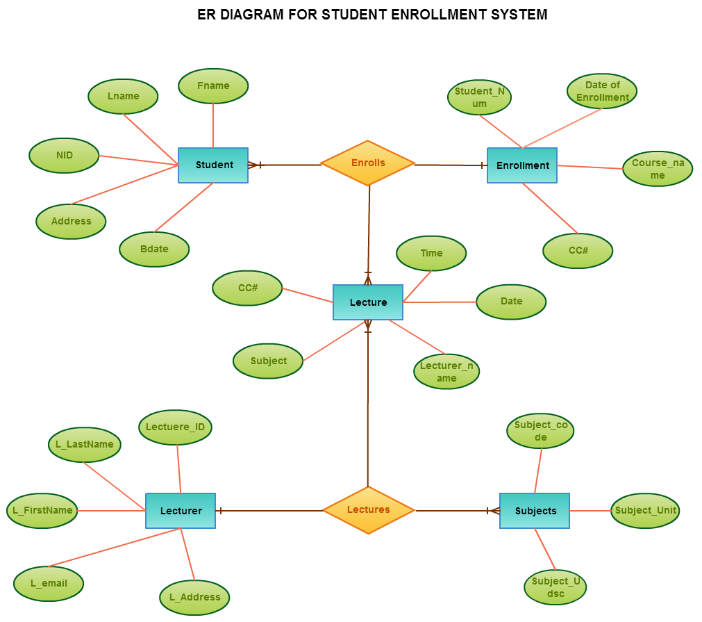
With dedicated shape libraries drag and drop standard ERD symbols onto the canvas within seconds. Entity-Relationship Diagram for a scenario involving Books Authors and Countries. Eg Freshman John is related to Student John This relationship.
A supertype can have any number of subtypes. Name is Key for Beers Beers. 10 min Entity relationship diagrams ERD or ER models represent the data in any system.
You can choose an automatic template called the Automatic ERD Database Diagram and generate your ER diagram using data from your database or choose one of the manual ERD templates included and design your database from scratch. This answer is not useful. Creating an entity-relationship ER model is to visually represent the structure of a business database where data equates to entities or objects that are linked by defined relationships expressing dependencies and requirements.
Creately diagrams can be exported and added to Word PPT powerpoint Excel Visio or any other document. Entity-relationship diagram ERD merupakan sebuah model untuk menyusun database agar dapat menggambarkan data yang mempunyai relasi dengan database yang akan didesain. ISA User - BuyerSeller classic Use Createlys easy online diagram editor to edit this diagram collaborate with others and export results to multiple image formats.
It is often useful to subdivide entities into classes like in an OOL If we declare A ISA B every A entity is also considered to be a. Lucidchart is the essential ERD tool to quickly differentiate relationships entities and their attributes. Freshman is a subtype of Student.
Connectors are always attached to shapes and. An Entity Relationship Diagram ERD is a visual representation of different entities within a system and how they relate to each other. Peter Chen developed ERDs in 1976.
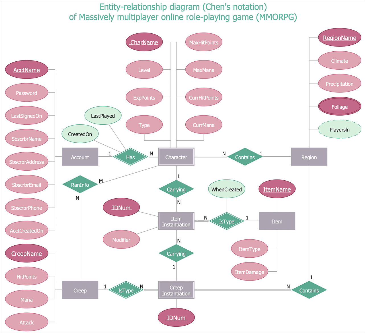
If the participation is instead optional which is not your case but lets put it for completeness then the 3 tables option is the way to go with a. Chens notation of the entity-relationship diagram depicts data and domain models using entities attributes and relationships. Spend more time coding and less time struggling to diagram.
ERD UML Tool Organization Chart Maker Floor Plan Designer Business Concept Diagram ITIL. Entity-relationship diagrams are incredibly useful and you can easily create one of your own by following these simple steps. You can edit this template and create your own diagram.
Entity Relationship Diagrams ERDs Relational Schemas Relational Diagrams Star Schemas Dimensional Models More features. Creating an entity-relationship ER model is to visually represent the structure of a business database where data equates to entities or objects that are linked by defined relationships expressing dependencies and requirements. Can be upgraded to paid editions for more diagram types and features.
To add descriptive attributes specific to a subclass. Our ER diagram tool simplifies database modeling whether your ERDs are conceptual or physical. This answer is useful.
A relationship exists between a Freshman entity and the corresponding Student entity. Online Erd Maker ER is a great-degree conceptual data product diagramEntity-Connection model is founded on the idea of true-planet organizations along with the relationship between them. Unlike other ER diagram notations it shows attributes as standalone boxes not as a part of entities.
The major entities within the system scope and the inter-relationships among these entities. Entity Type Hierarchies. Heres how to create them with drawio.
By nature it is an abstract visualization the first step in the design process towards creating a logical and functional database. Common Entity Relationship Diagram Symbols. Show activity on this post.
One entity type might be a subtype of another--very similar to subclasses in OO programming--which inherits the attributes and relationships of the first entity.
Entity Relationship Diagram Erd Er Diagram Tutorial

Komentar