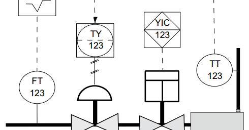
1 recorder 2 transmitter 3 converter. - 3 - ANSIISA-51-2009 Preface informative This preface is included for information purposes and is not part of ANSIISA-51-2009.
Electro Magnetic World Isa Symbology
State the type of control typically used and explain why it is used Identify and describe considerations for equipment selection eg speed.

Compponents of control loops and isa symobology. Components of control loops and ISA symbology. The basic function of a _____ is to convert a reading from a transducer into a standard signal and transmit that signal to a controller or computer monitor. T represent transmitter used to measure variable for example FT is used to measure flow fand C is used to controller for example LIC is.
Control loop a variable temperature fell below the setpoint your comfort level and you took action to bring the process back into the desired condition by adding fuel to the fire. LLANOSGiovanny Earl C. The ISA has developed a set of symbols for use in engineering drawings and designs of control loops ISA S5.
A The components of control loops are transmitter and controller and final control element that is control valve. Of 1 Components of Control Loops and ISA Symbology ISA Symbology The Instrumentation Systems and Automation Society ISA is one of the leading process control trade and standards organizations. Differentiate feedback and feedforward control loops in terms of their operation design benefits and limitations Perform the following functions for each type of standard process control loop ie pressure flow level and temperature.
Other principal components of the loop to be shown and identified under ISA-S51 Instrumentation Symbols and Identification. Greatest ingenuity in the process control field is apparent in sensing devices. We review their content and use your feedback to keep the quality high.
Inaccessible behind the panel devices may be depicted using the same symbol but with a dashed horizontal bar. 18-51873 PetE 3201 March 26 2021 EXERCISE 73 COMPONENTS OF CONTROL LOOPS AND ISA SYMBOLOGY 1. 1 instrumentation symbol specification.
Components of control loops and ISA symbology. The first identification letter is for the measured value the second is a modifier 3rd indicates passivereadout function 4th - activeoutput function and the 5th is the function modifier. Apply specific ISA standards to interpret symbols and drawings associated with process control.
In addition this section describes how process control equipment is represented in technical drawings of control loops. PRIMARY ELEMENTSSENSORS In all cases some kind of instrument is measuring changes in the process and reporting a process variable measurement. Because sensing devices are the first element in the control loop to measure the process variable they are also called primary elements.
Uni2751 A heavy solid line represents piping uni2751 A thin solid line represents process connections to instruments eg impulse piping uni2751 A. In some cases the drawing includes an overview of the closed loop and manual control calculations and measurements that will be implemented in the control system. Learning objectives Primary elements sensors Transducers and converters Transmitters Signals Indicators Recorders Controllers Final control elements Actuators ISA symbology CONTROLLER ALGORITHMS AND TUNING Controller algorithms and tuning - Learning objectives Controller algorithms.
This standard has been prepared as part of the service of ISA The International Society of Automation. Manual control Plant operator adjustment of a process input. Learning objectives Start Primary elements sensors Start Transducers and converters Start Transmitters Start Signals Start Indicators Start Recorders Start Controllers Start Final control elements Start Actuators Start ISA symbology Start CONTROLLER ALGORITHMS AND TUNING 7 Lessons.
Pressure sensing diaphragms strain gauges capacitance cells. In 2nd Chapter of this book includes information components of control loop and ISA symbology. Resistance temperature detectors RTDs.
Examples of primary elements include. Precise control of leveltemperature pressure and flow is important in many process applications. If not adequate use a supplemental note.
2 Word description of loop functions within the title. In 5th Chapter of this book describes single loop control and feedback control loops. In 4th Chapter of this book is comprehensive guide to process control loops.
In 3rd Chapter of this book covers controller algorithm and tuning. Demonstrate the operation of components required for closed-loop control Review start-up procedures for single- and multi-loop systems Tune cascade ratio. Multi-Variable Advanced Control Loops.
Closed loop control - Automatic regulation of a process inputs based on a measurement of process output. Abbreviations of the users choice may be used when necessary to specify location. Control in process industries refers to the regulation of all aspects of the process.
The ISA has developed a set of symbols for use in engineering drawings and designs of control loops ISA S51 instrumentation symbol specification. The Instrumentation Systems and Automation Society ISA is one of the leading process control trade and standards organizations. View the full answer.
Controller Algorithms and Tuning. Data from ISA S51 standard. Components of Control Loops and ISA Symbology.
Symbol size may vary according to the users needs and the type of document. 1 Identification of the loop and loop components shown on the PIDS. This is followed by loop number which is unique to that loop.
The control loop will now remain static until the temperature again rises above or falls below your comfort level. For instance FIC045 means it is the Flow Indicating Controller in control loop 045. THREE TASKS Control loops in the process control industry work in the same way.

P Symbols Library 220 Autocad Symbols Autocad Symbols Library


Komentar